It’s often believed that in order to achieve a linear depth buffer, one needs to counter the W division by multiplying the Z component of the position before returning the vertex shader:
outPos.z = (outPos.z * outPos.w - nearPlane) / (farPlane - nearPlane)
At least that’s what I thought too for a very long time, ever since I read Robert Dunlop’s article on linearized depth. The author goes further by tweaking the projection matrix cpu side so that all you have to in the vertex shader is:
outPos.z = outPos.z * outPos.w
Which is a nice trick. The thing is, the results are not really linear.
What is linear?
Before I can continue, we first need to understand what we mean by “linear”. In the 3D jargon; when one speaks about linear depth buffers, he’s usually referring to being linear in the view space domain.
Just like Emil Persson talks in his blogpost A couple of notes about Z; the usual “z / w” projection is linear too; but it’s linear in the screen space domain. The problem with z values being linear in screen space is that they offer awful precision when getting far away from the viewer and the smaller the value of the near plane is; whereas depth values linear in view space have a much more uniform precision distribution.
So whenever we talk about “linear depth”, we’ll be referring to depth values being linear in view space.
Some math behind the trick
The idea behind the trick in question is that the GPU will later divide by W. So in theory Z / W * W = Z.
But we’re forgetting something: values are interpolated during rasterization. Normally, this operation happens in the GPU (simplified, as 3 vertices are actually being interpolated, not two):
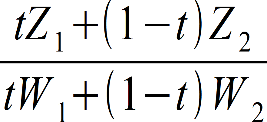
In order to achieve a truly linear depth value, the multiplication and cancellation should be as follows:
![tZ_1 + (1-t)Z_2 = {[tZ_1 + (1-t)Z_2] * [tW_1 + (1-t)W_2]} over {tW_1 + (1-t)W_2}](https://yosoygames.com.ar/wp/wp-content/uploads/2013/09/LinearDepthMyAss02.png)
Which is impossible to achieve from the vertex shader because we don’t have knowledge of the other 2 vertices, and we are not in control of the t variable (which in this equation stands for the interpolation weight) unless someone finds out how to cancel it in that equation from the VS.
Instead, with the proposed “trick”, this is what we end up doing:
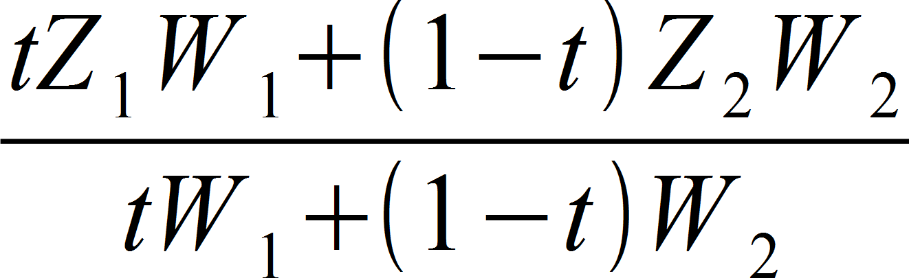
Now it’s clear there’s no real cancellation unless W1 = W2 or t = 0 or t =1; the value is not truly linear in view space. However, we can tell it is different, which can explain that as t approaches 0 or 1, that is as we get close to the triangle’s edges, precision starts to improve.
The only way to write true linearized depth is to use the depth out semantic in the pixel shader, which turns off Z compression, Early Z, Hi-Z and other optimization algorithms employed by the GPU. And by the way, if you’re going to have all those disadvantages, you’re better off with logarithmic z-buffer whichs has insanely high precision.
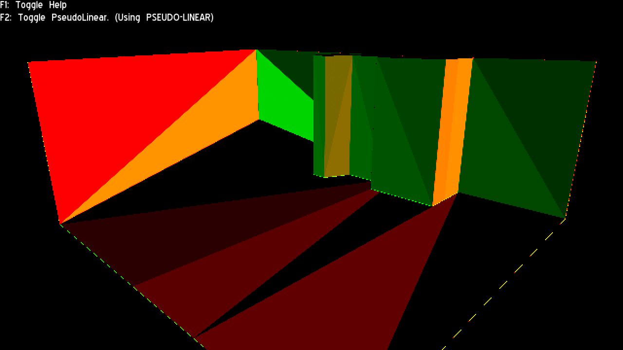
To further verify this mathematical analysis, I made a special shader that shows ddx in R channel and ddy in G channel (scaled to a visible range):
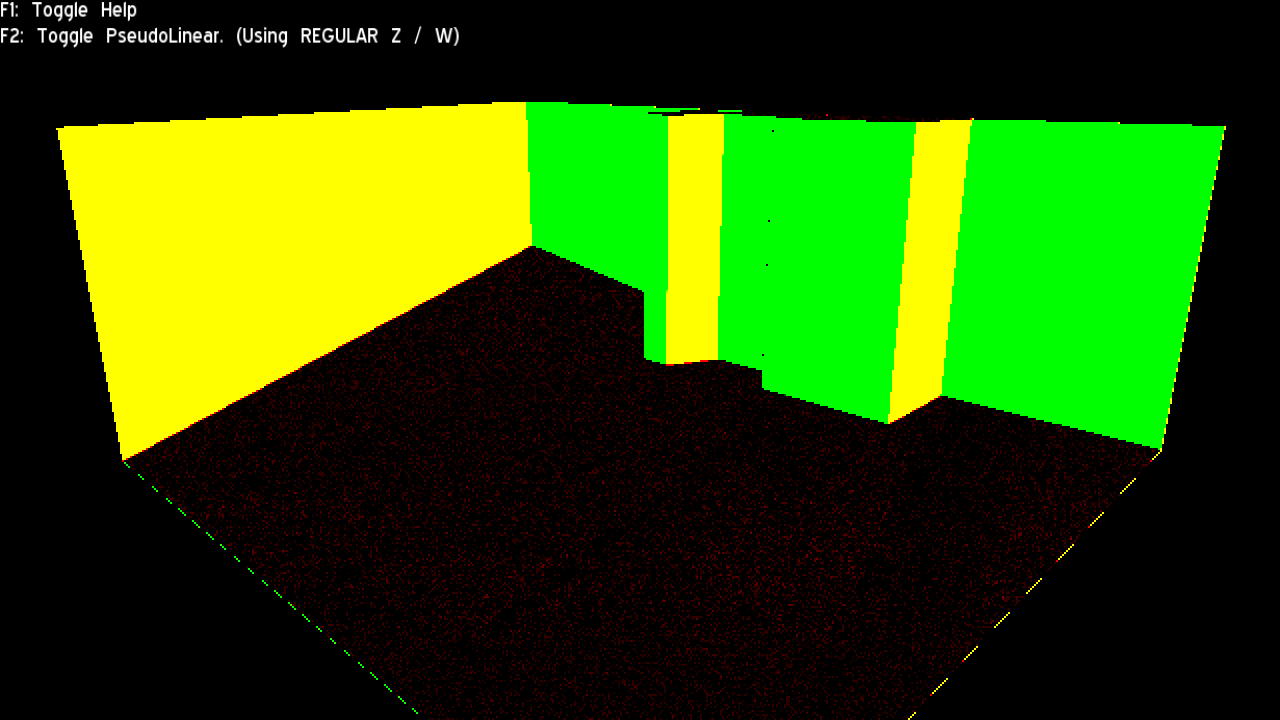
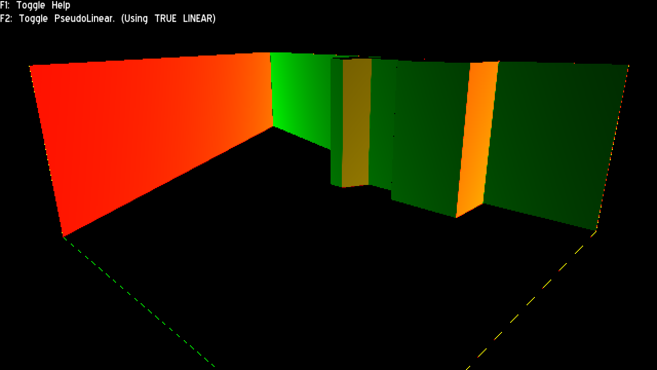
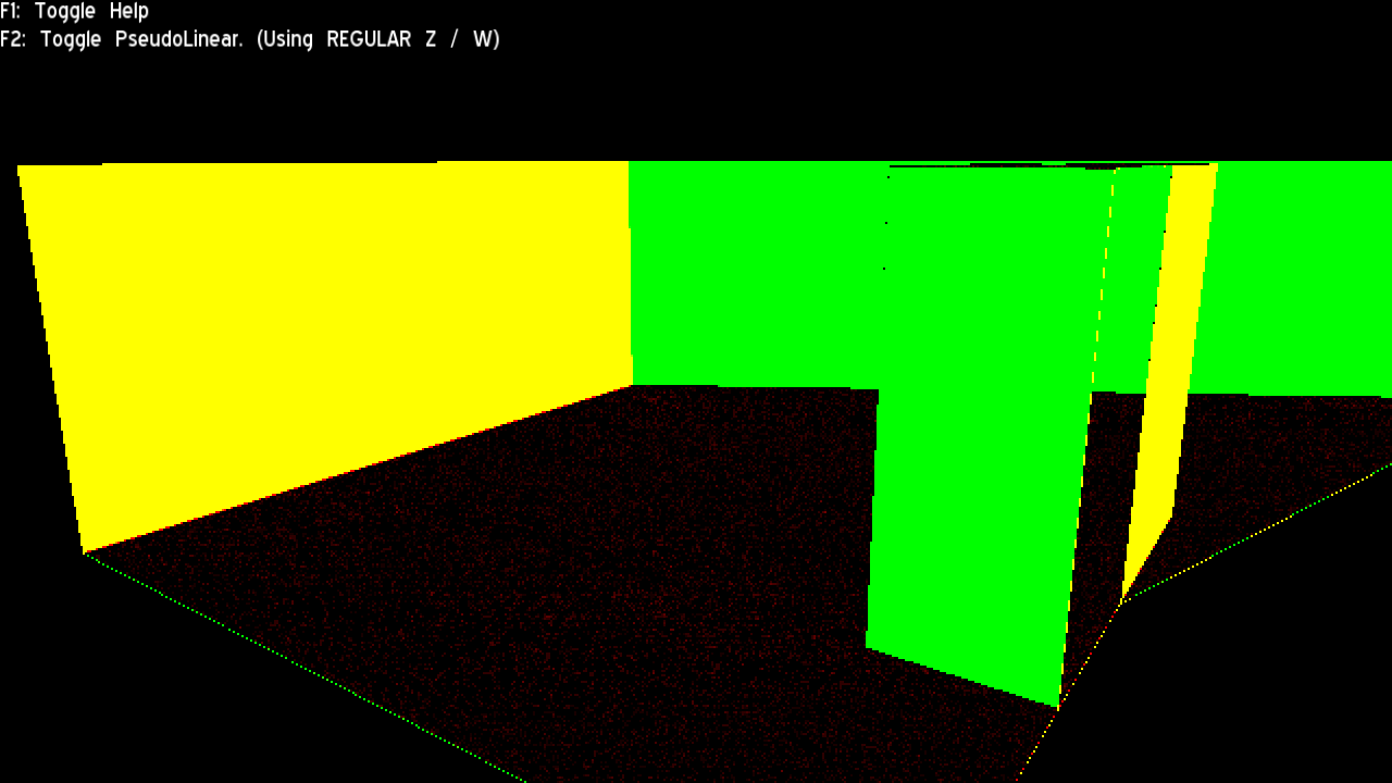
The regular version looked just as expected: A solid colour across all triangles aligned to the same plane. This means the derivative is constant and all rasterization assumptions are met (for compression, Hi Z, etc)
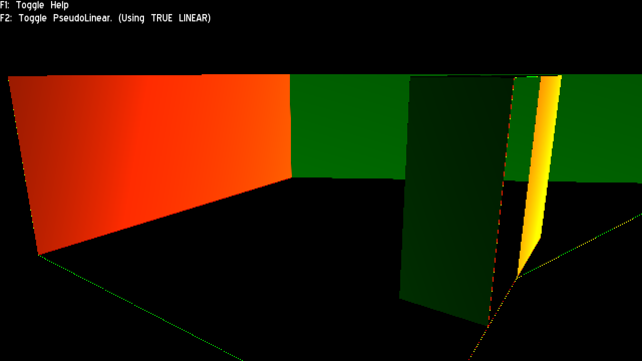
The true linear version also looks as expected: A gradient (btw, I wonder if the 2nd order derivative is constant, which if true, theoretically it would mean linear depth buffers could be compressed and used in Hi Z with just a bit of additional overhead; I did not research into that though; besides the linear depth method would have to be provided by the HW)
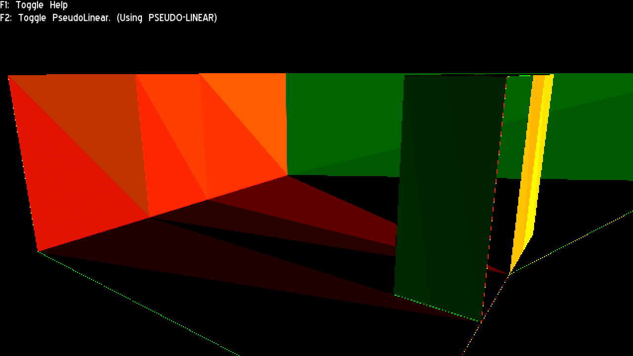
The “Pseudo linear” version (aka the subject of this post) did NOT look as I expected: I was expecting to find the same look as the regular Z/W version just different colours (the constant is different). But instead, visible triangulation appeared. At first, I thought it was due to the model being exported using flat normals, which leads to duplicated vertices. But after trying again with the same model using smooth normals, the triangulation persisted.
My statement still states correct though: The stored depth is still indeed non-linear and compression friendly. However it is not as friendly as I hoped: The triangle pattern breaks a lot of blocks that would be compressed otherwise.
What causes this triangle pattern? I’m not sure, but my guess is that since the pseudo linear trick is just the equivalent of a Z-scale skewing/shearing that depends on the W value at render; the placement of the 3rd vertex (the one not shared by two adjacent triangles) will skew the triangle by different factors despite (and throwing it out of its original plane).
Best or worst of both worlds?
So, we have Z/W in one end which is very optimization friendly but highly inaccurate, and true linear Z on the other (and Log(Z) in the very far extreme) which can be very accurate but doesn’t optimize at all.
And in the middle we have the pseudo-linear version which offers midground accuracy and may take advantage of all optimizations in some scenarios, or none of them in others (depends on triangle density, how many triangles lay on the same plane, and covered area in pixels).
Clearly if common scenarios prevent most depth optimizations, devs will just prefer to use the pixel shader’s depth out semantic to get more accuracy.
But if common scenarios often still take advantage of depth optimizations, then the pseudo linear trick improves accuracy almost for free.
What is the common scenario? I’m afraid profiling and analyzing real world data seems the only answer.
Downloads
I’ve uploaded the exe I’ve made to perform this experiment. It comes with source code. Requires Ogre 2.0
Yosoygames Mirror – MediaFire Mirror
In glspec is says that associated with vertex datum is interpolated in perspective correct manner right as you said.
But:
However, depth values for polygons must be interpolated by
z = a*Za + b*Zb + c*Zc (14.10)
Please look in OpenGL registry.
Also from this https://www.comp.nus.edu.sg/~lowkl/publications/lowk_persp_interp_techrep.pdf
“Equation (12) tells us that the z-value at point c in the image plane can be correctly derived by just linearly interpolating”
What do you think?
The paper seems to be about achieving perspective correct interpolation by linear interpolation in the SCREEN SPACE. As the first parragraph says.
This does not contradict my article at all. I said:
“the usual “z / w” projection IS LINEAR TOO; but it’s linear in the SCREEN SPACE domain.”
While my article talks about trying to get linear depth in VIEW SPACE.
View space and screen space are two different spaces. Either you’re linear in screen space, or you’re linear in view space. It’s not contradictory.
In your article you give interpolation formula for Z value with W in denominator.
But in https://www.opengl.org/registry/doc/glspec45.core.pdf
is says that Z values are rasterized like (14.10) page 456:
z = a*Za + b*Zb + c*Zc
So your further visualizations with dFdx are not corresponding to how Z values are rasterized in depth buffer.
Thus writing in vertex shader
outPos.z = Z_in_view_space * outPos.w;
will give true linear depth buffer for view space.
I’m sure I’m missing something again, please correct me))
I’m pretty sure I’m not wrong, but you left me hanging with a bit of a doubt. Depth precision is a hard topic.
I would have to port the sample to D3D11 and read the contents from the depth buffer directly to prove it 100% beyond any doubt.