So… it’s hard to ignore yesterday’s announcement of Unreal Engine 5 with a very impressive demo
There’s a lot of chatter about how they’re doing and like Angelo said, proving that something is possible suddenly inspires other people to come up with their own ideas.
So I am going to do my own take on how I think they’re doing it. And while UE5 may not be rendering things exactly this way (or completely different?), I think this algorithm that popped into my mind yesterday during my sleep after watching the video would have a really good chance.
Once an idea screams in my head, I need to write it down or implement it.
The problem
Rendering millions of triangles in realtime. Ideally converging into the order of approximately 1 triangle per pixel, but we need to define it as N pixels per triangles more or less spatially homogeneously distributed.
Feeding DrawPrimitive() with a model of a billion triangles doesn’t work. Simply because there’s a lot of vertex shader wasted, and the rasterizer can’t keep up with the amount of triangles that need to be rejected. At 1080p there’s only 2 million pixels. Processing more triangles than that means wasted effort.
Constraints and goals
We need to define a series of constraints and goals:
Constraints
- Static geometry only. Instancing may be possible though (e.g. 1000 of statues arbitrarily placed at runtime). But no animation.
- Input data should ideally be incredibly dense. Z-Brush sculpts and Quixel Megascans are perfect for this. Low poly inputs should also work but those are probably rendered best traditionally.
- Near-infinite offline preprocessing. Obviously quick offline processing means faster iterations. But we’re willing to spend time doing offline optimizations if the algorithm requires it.
Goals
- Render a near-constant amount of triangles per frame, directly proportional to screen resolution. This goes in line with the idea of N pixels per triangle.
- Multiple materials should also be supported
- Transparents seem to be supported by the algorithm, but they’re not really a goal
Algorithm
The algorithm consists in two steps: offline processing and realtime rendering.
From a very general overview this algorithm is conceptually simple:
- Group triangles spatially into chunks offline
- At runtime raymarch/conetrace which chunks are visible by pixels
- Render the triangles in those chunks
When I think about it, it’s just a fine-granularity variation of occlussion culling.
Of course, the devil is in the details.
Offline processing
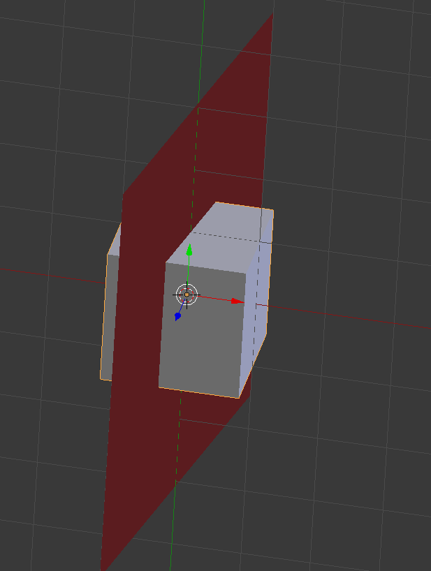
- The input geometry is spatially subdivided in a 3D grid. Triangles which cross cell boundaries will need to be subdivided (possibly there are other alternatives, but this is what I’m coming up with for now) (*)
- For each non-empty cell:
- Generate a list of triangles (split by material)
- Generate lists of LOD
- Optional: Throw lots of rays (brute force) from all 6 directions (or more) to tag which triangles aren’t visible when viewed from each direction. There may be clever ways to arrange triangle lists:
- Place tris viewable from all directions first, so that compute shaders in realtime can assume these tris can always be included
- Generate 7 lists (1 general list, then 1 list per direction containing tris that are only visible from that direction)
- If a voxel is 100% inside a triangle, tag this voxel as ‘blocker’ from the directions it blocks
- Use a Sparse Voxel Octree (SVO) to hierarchically group the non-empty cells, and to prevent wasting massive memory on empty cells. Note that the higher mips/nodes of the SVO also need to have lists of triangles from their children, but only keeping the higher LOD levels.
- Create a low poly hull (doesn’t have to be convex) that encloses all this geometry as tight as possible. It’s no different from low poly models used in occlussion culling tests. They need to be approximate and can overestimate, but never underestimate.
(*) There are other possible solutions, such as geometry images which quantizes geometrical points into pixels in a 2D grid. This solves the triangles crossing boundaries problem, and could play better with LOD mismatches (e.g. a block of 4×4 pixels using LOD1, while neighbour block of 4×4 pixels using LOD0). This has been linked to UE5.
Thus, after this algorithm, we have an SVO containing lists of triangles inside. We can select LODs at each mip. If we need higher detail, we go to a lower mip which contains a lower LOD. And we have the hull.
Realtime Render
We define the algorithm’s resolution (independent from rasterization’s resolution). We could e.g. do 1/4th of the resolution and thus trace one cone per pixel to cover lists of triangles that should cover 8×8 pixels. Larger blocks This allows us to trade off quality vs performance.
Lower algorithm resolution means bigger triangles and quicker cone tracing phase.
We need two temporary R32_FLOAT depth textures: depth0 and depth1. We will assume depth = 0.0 closets to camera. If using reverse Z, some of these operations will need to be inverted. Both targets need to be at algorithm’s resolution.
Steps 1 through 4 are an acceleration step and aren’t strictly required
- Clear depth0 to 1.0
- Clear depth1 to 0.0
- Render to depth0 the low poly hull’s front faces with depth_func set to less.
- Render to depth1 the low poly hull’s back faces with depth_func set to greater.
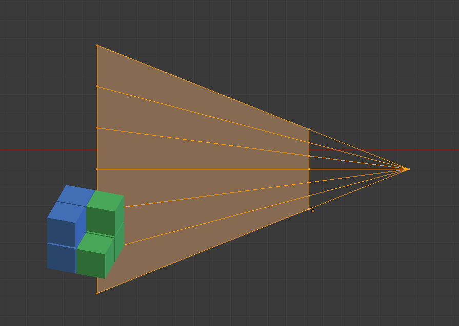
- Run a Compute Shader (CS) which will use cone tracing from camera to find a hit against the SVO. The cone trace doesn’t have to start from camera’s position: That’s why we have the hull’s depth! We know we can start from depth0, and we also know to stop when we reach depth1. For each pixel block, cone trace:
- If a voxel is hit, append to a list and continue cone tracing unless the voxel is tagged as blocker from our direction.
- Repeat previous step until we reach depth1
- The maximum tree depth we look into decreases as the ray moves away from camera, and so does inversely increase our cone step size.
- Run another CS to filter out duplicate entries in the list, assuming it was impossible to use atomics efficiently in step 5 to guarantee each list only gets added once.
- DrawPrimitiveIndirect() the lists of triangles produced by steps 5 & 6.
- Alternatively, the use of 4 clipping planes during raster could be explored to limit each triangle to the block of pixels it should be contained in. e.g. a triangle spanning multiple blocks 8×8 could be processed by multiple 8×8 blocks and each block limits the rasterizer to their own [x,y,width, height] bounds.
Avid Graphics devs will already have figured out that for an algorithm resolution that matches 1:1 with final resolution we’re effectively doing an overly complicated raytracing: for each pixel shoot 1 ray, if it hits a triangle, it gets rendered. Raytracing is far simpler. The advantage here is that we can shoot at a different resolution.
Temporal optimization
Using temporal reprojection of depth0 and depth1, we can infer that if their differences don’t exceed certain thresholds we can reuse the lists calculated for that pixel from the previous frame, no need to cone trace.
Adaptive cone tracing (temporal)
If temporal suspect the list is out of date, we may decide to shoot cones at 16×16 resolution for that region, instead of 8×8 thus using higher LODs.
Adaptive cone tracing (non-temporal)
The low poly hull could output more than just depth info. For example areas that don’t require high tessellation can be marked as such (either by artist or automatically), and if we see a 16×16 block fully covered by low tesssellation, we shoot 1 cone for the whole 16×16 instead of 4 cones for each 8×8 region.
Instancing
The algorithm described assumes there is only 1 hull and 1 SVO. However there is no such limitation.
By instancing we mean ‘arbitrarily placing copies of the same mesh at different locations with little additional memory cost’
There are several ways instancing could be supported:
- By creating a master SVO which references into multiple SVO. Its hull could be a CSG boolean operation of the individual hulls. Slower at runtime but near 0 offline
- By baking everything into one SVO and hull. Slower at offline, large memory cost (not really instancing) but faster at runtime.
- By rendering each hull into the same depth buffer and evaluating each SVOs per pixel in the CS. Much slower at runtime but 0 offline cost.
Potential problems
This is just an idea. I haven’t implemented it, but I can foresee:Getting cone tracing right. This is always a PITA until it works.
1.- Getting cone tracing right. This is always a PITA until it works.
2.- Duplicate overlapping geometry due to aliasing. If pixel0 determines we should use voxel0000 and pixel 1 determines we should use voxel000 (higher lod), both pixels would send different lists of triangles but voxel000’s tris will overlap with voxel0000.
This picture ilustrates the problem:
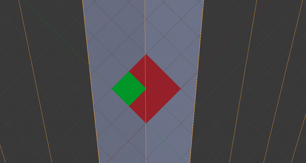
Depends on how troublesome this problem is, we could tune the parameters until it’s rare, ignore it, or spend time cleaning out children from neighbour pixels that belong to an already included parent.
3.- Holes. It’s the opposite problem: Small voxels being ignored by the cone trace. I’m not too concerned about this because in regular rasterization this problem exists too (tiny sub pixel triangles popping in and out of existince as the camera rotates), and if the ray from a cone ignores the edge of a large block that is far away, then its neighbour pixels will almost definitely get it. But it could happen.
Many of this issues can be resolved using clipping planes, as clipping planes get rid of duplicate triangles creeping outside the 8×8 block, but at the expense of more processing time during runtime. But I’d expect there would be an upper limit on how costly that is (i.e. it’s not unbounded).
4.- Streaming. Billions of triangles like Quixel Megascans’ weight 2GB of data or more. We can’t load everything at once. Paging things in and out becomes key. And clever use of mips and LODs while higher quality data arrives is key. The use pinned memory can be a PITA to manage at multi-platform level.Once the algorithm is right, this will become by far the biggest recurring problem; and affects all algorithms (and I bet UE5 too) since its a technical implementation detail, that has little to do with the algorithm. And from a non-technical aspect, I don’t think users will like their 0.87TB SSD (PS5’s announced drive size) being taken over by one or two games.
Well… that’s it. It’s out of my head. I have a billion other things to do so I don’t think I will be implementing it soon unless someone pays for it. But I might one day.